
Launch Tube
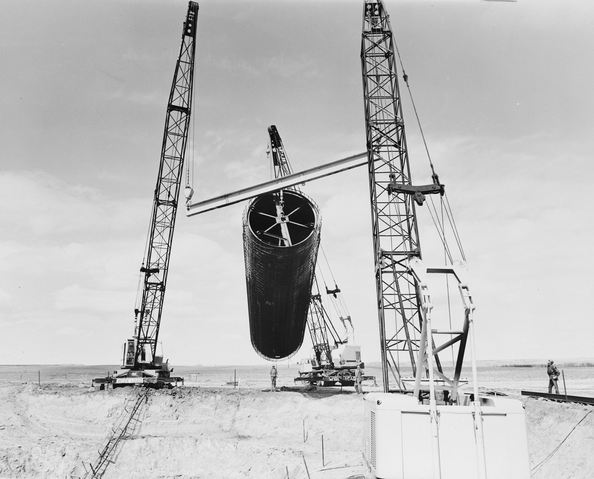
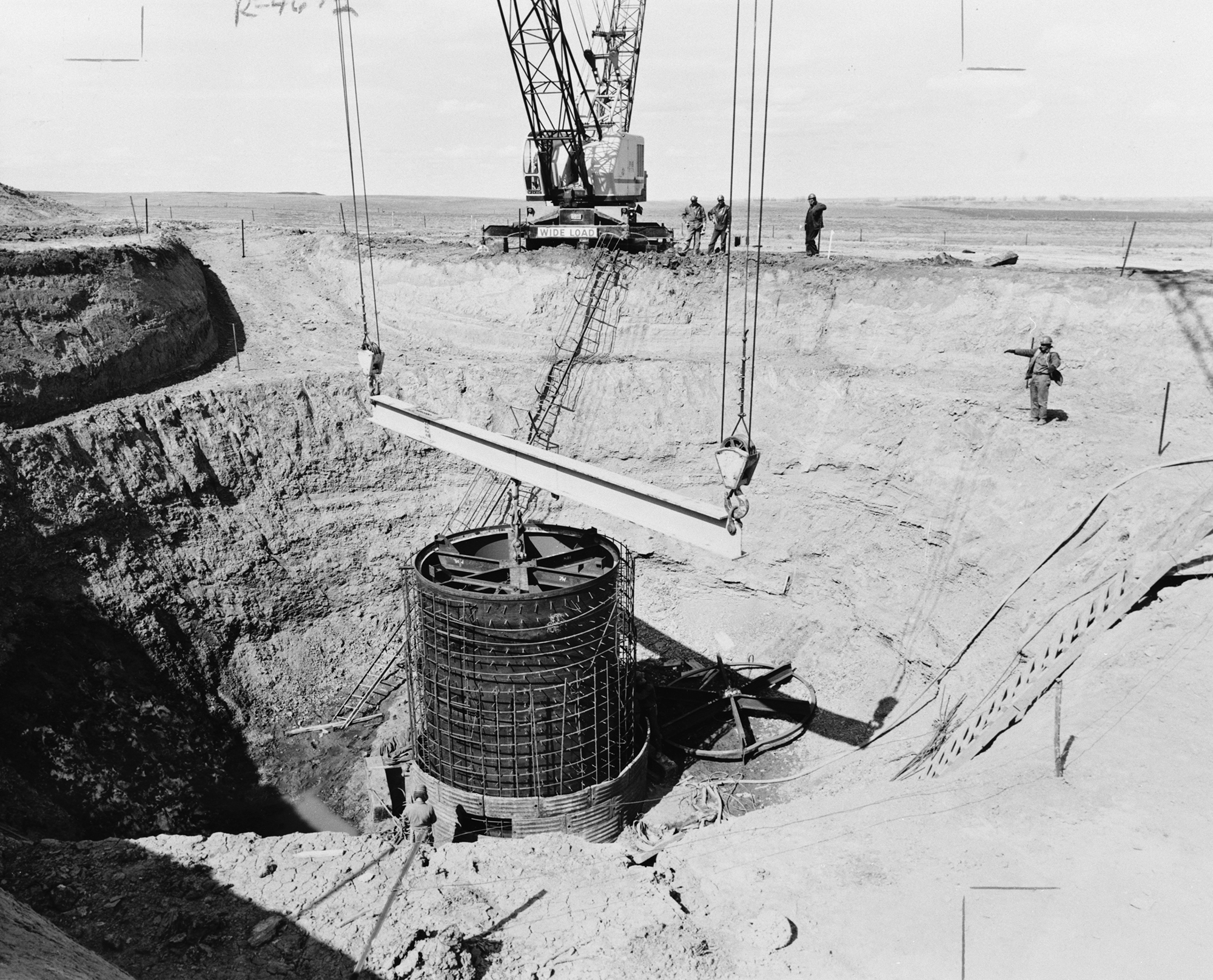
Launch Tube Ready For Placement
Click on the image for a larger view
Launch Tube - Launch Facility
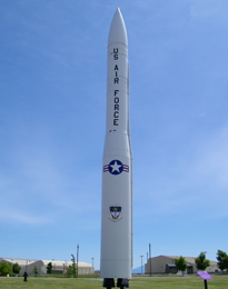
The Launch Tube serves the purpose of a humidity and temperature controlled structure that provides a protective housing that combines both a launch support facility and structure. The Launch Tube also functions as a launch pad for the Minuteman missile. The Launch Facility is comprised of an underground Launch Tube (missile silo) that is surrounded by a cylindrical upper and lower equipment room providing the Launch Facility the capacity to house, monitor, and launch the missile within short notice. Thus the terminology - Minuteman missile. The Launch Tube is covered by a hardened, three and a half feet thick, Launcher Closure Door weighing 110 tons.
The Launch Tube is basically a reinforced concrete cylinder that is lined with quarter inch thick steel plate. In the images above and below, you can see the iron rebar frame of the Launch Tube as it is lowered into place. Reinforced concrete will be poured into place once the rebar frame is prepared. The Launch Tube measures 25 feet in diameter and is close to 80 feet deep. The Launch Tube sits on top of a four feet thick reinforced concrete foundation. From the bottom of the Launch Tube extending 46 feet up is designed with about 10 inches of heavily reinforced concrete encasing the Launch Tube. On the floor of the Launch Tube sits a 2 inch thick steel plate that functions as a blast deflector for the missile's exhaust once it is launched.
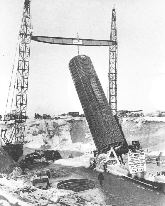
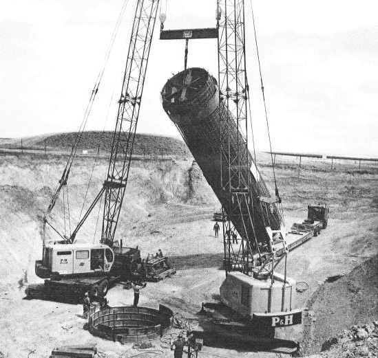
Launch Tube Ready To Be Placed - Grand Forks AFB
Missile Suspension System
Located approximately 21 feet above the floor of the Launch Tube are a series of pulley blocks welded to the walls of the Launch Tube. These pulley blocks make up the three point suspension system that is designed to absorb any significant impact to the Launch Facility, protecting the Minuteman missile from any damage from a nuclear detonation.
This shock absorbing suspension system has a large free-floating steel ring that is placed on the bottom of the missile, which allows the missile to sit upon that steel ring. This ring is attached to three steel wire cables. The cables extend upwards and pass up and over the pulley blocks that are welded to the wall of the Launch Tube. The other end of the cables are anchored to large, spring coil type shock absorbers that are bolted to the base of the Launch Tube.
To view additional photographs of the Launch Tube, as well as photographs of the upper and lower Launcher Equipment Rooms, please follow the link below.
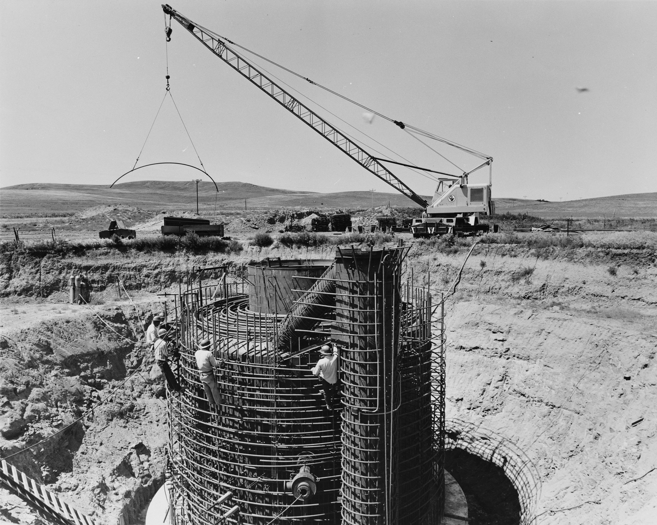
Close Up Of Launch Tube and Liner
Click on the image for a larger view
Note the Launch Tube in the center of the rebar frame
Two Level Equipment Room
Encompassing the upper section of the Launch Tube are a cylindrical Upper and Lower Equipment Room, that is comprised of heavily reinforced concrete with a steel liner. The Equipment Room measures approximately 25 feet by 15 feet, is 28 feet deep and has a 4 feet thick concrete foundation. The walls of the Upper and Lower Equipment Rooms are 2 feet thick concrete.
Incorporated into its design is a 6 inch "rattle space" located between the Equipment Rooms and the Launch Tube itself, which allows for the two structures to move independently of each other.
To view additional photographs of the Launch Tube, as well as photographs of the Upper and lower Launcher Equipment Rooms, please follow the link below.
Launch Tube Close To Being Fully Placed
Click on the image for a larger view
Lower Level Equipment Room
The Lower Level Equipment room houses a total of 12 large storage batteries. These batteries are a part of the design implemented at the Launch Facility, should the commercial power go out, and the emergency generator in the Launch Support Building does not work.
Found also in the Lower Level Equipment Room is the power panel for the weapon system of the Minuteman missile. Next to this electrical power panel are a number of surge arrestor components tied into the electrical equipment. These surge arrestors were installed to insure that the electrical equipment inside the Launch Facility does not become damaged from electromagnetic pulses resulting from a nearby nuclear explosion.
Also housed in the Lower Equipment Room is the large cylindrical ballistic gas generator used to generate the high pressures needed in opening the 110 ton Launcher Closure Door. The piping and integral equipment of the gas generator extends up through the upper level floor.
To view additional photographs of the Launch Tube, as well as photographs of the Upper and Lower Launcher Equipment Rooms, please follow the link below.
Launch Tube Liner Malmstrom AFB May 1965
Upper Level Equipment Room
The Upper Level Equipment Room houses a framed platform made of steel, which is covered by a steel deck plate. On the outer wall sits a bench also made of steel, that is marked with compass bearings. This bench was referred to as the autocollimator bench. The autocollimator bench was first installed back when the Air Force had to use a very complex alignment system, which was essential in calibrating the targeting system on the Minuteman missile.
Attached to the autocollimator bench was the actual autocollimator, which is also referred to as a theodolite. This is essentially a piece of equipment similar to a surveyors tool. The autocollimator is no longer in use, given the reconfiguration of the Minuteman missile system and is now fully automated through the use of computer equipment.
Just above where the autocollimator was placed sits a round porthole called a sight tube. This sight tube provided the means for the targeting technicians to beam a light down into the Upper Level Equipment Room. This design allowed the technicians to establish visual references from two concrete azimuth markers that were placed on the surface in a field outside of the Launch Facility security fence. These azimuth markers were placed apart from each other approximately 1/4 of a mile away from the LF. During the calibration of the Missile Guidance System, a battery operated light was placed on each of these markers, allowing the targeting technicians to establish a visual reference of where the missile sits inside the silo, and the location of the North Star, in relation to the missile.
Of note, in following the link to the photographs of the Launch Tube and Launch Equipment Rooms, if you examine the photograph of the missile sitting atop of the large steel ring that comprises the Missile Suspension System, you can see that the ring has teeth forming what looks to be the steel teeth of a large gear. This allowed the guidance technicians to literally turn the missile in configuring the targeting system in relationship to where the North Star (Polaris) is in relationship to that specific missile.
Approximately one third of the Upper Level Floor is attached to a number of shock struts that are coiled springs in design, of which are attached to the ceiling. The floor in this section is designed to absorb shock, given the need to protect a number of racks of electronic equipment and computers that are designed to monitor the missile, communicate to the Launch Control Center, and prepare the missile for launch.
To view additional photographs of the Launch Tube, as well as photographs of the upper and lower Launcher Equipment Rooms, please follow the link below.