
Upper Launcher Equipment Room
Autocollimator Bench
Click on the image for a larger view
Missile Targeting Procedure
One of the most important components found in the Upper Launcher Equipment Room is the concrete bench built into the wall of the equipment room. This bench supported the collimator, used in the targeting procedure for the Minuteman missile.
There are a three part series of articles written by retired Air Force targeting specialists, that describe the procedure that was followed, during the years they were in the Air Force and formed a part of the incredible work teams who were servicing the early versions of the Minuteman missile.
For the interested reader, those articles can be viewed in pdf form, which are found on the AAFM, Association of Air Force Missileers' website, in their newsletters sections. Part 1 is dated December 2006. Part 2, March 2007, and Part 3 June 2007.
The Association of Air Force Missileers (AAFM) is an incredible organization that welcomes civilians, as well as retired and active military individuals to join their organization. They provide a profound wealth of information on the ICBM program overall, (Atlas, Titan and Minuteman and others) and these AAFM members are simply fabulous people you can get to know, as well as meeting these individuals at the AAFM National Meeting, which is held every two years.
Follow the link below to access those articles.
The ring pictured above was a crucial part of the targeting and alignment system in the early versions of the Minuteman missile. To this writer, the process of the targeting and alignment of the missile was a very complex, detail oriented and time consuming process that took early technicians in the Air Force hours to complete. (Of which it is suggested to take a look at the articles mentioned above to better understand this process.)
The targeting and alignment process required the use of two theodolites at the Launch Facility. One theodolite was situated in the Upper Launcher Equipment Room. The second was located topside, on the surface of the LF. This second theodolite was attached to an External Concrete Alignment Monument, which was located just forward and to the side of the Launcher Closure Door.
Below are three photos of one of the External Concrete Alignment Monuments at the P10 Launch Facility, that was a part of the 564th Strategic Missile Squadron attached to Malmstrom AFB. The Air Force deactivated the 564th SMS starting in 2007.
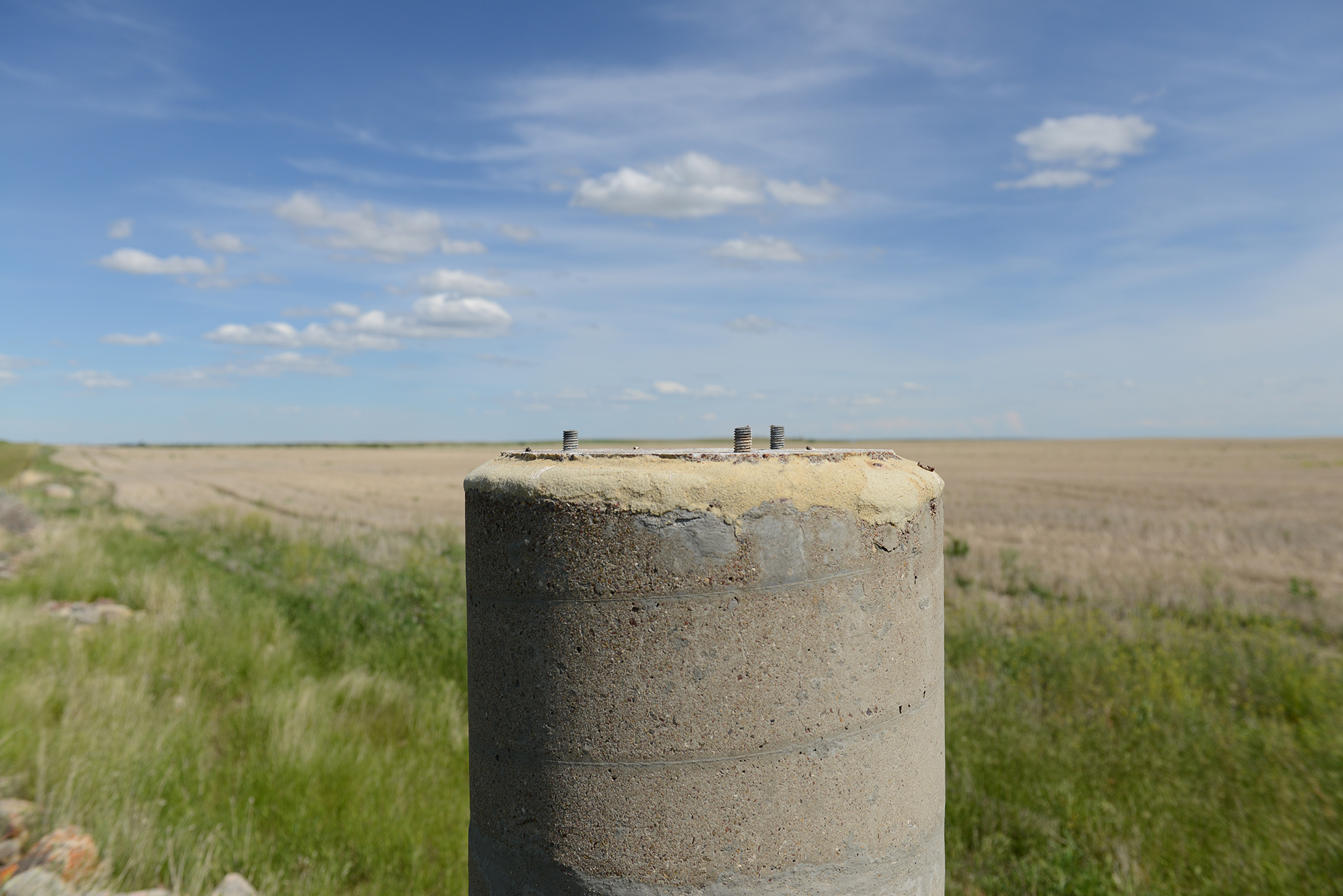
P10 Launch Facility External Concrete Alignment Monument
Click on the image for a larger view
P10 Launch Facility Concrete Alignment Monument
Click on the image for a larger view
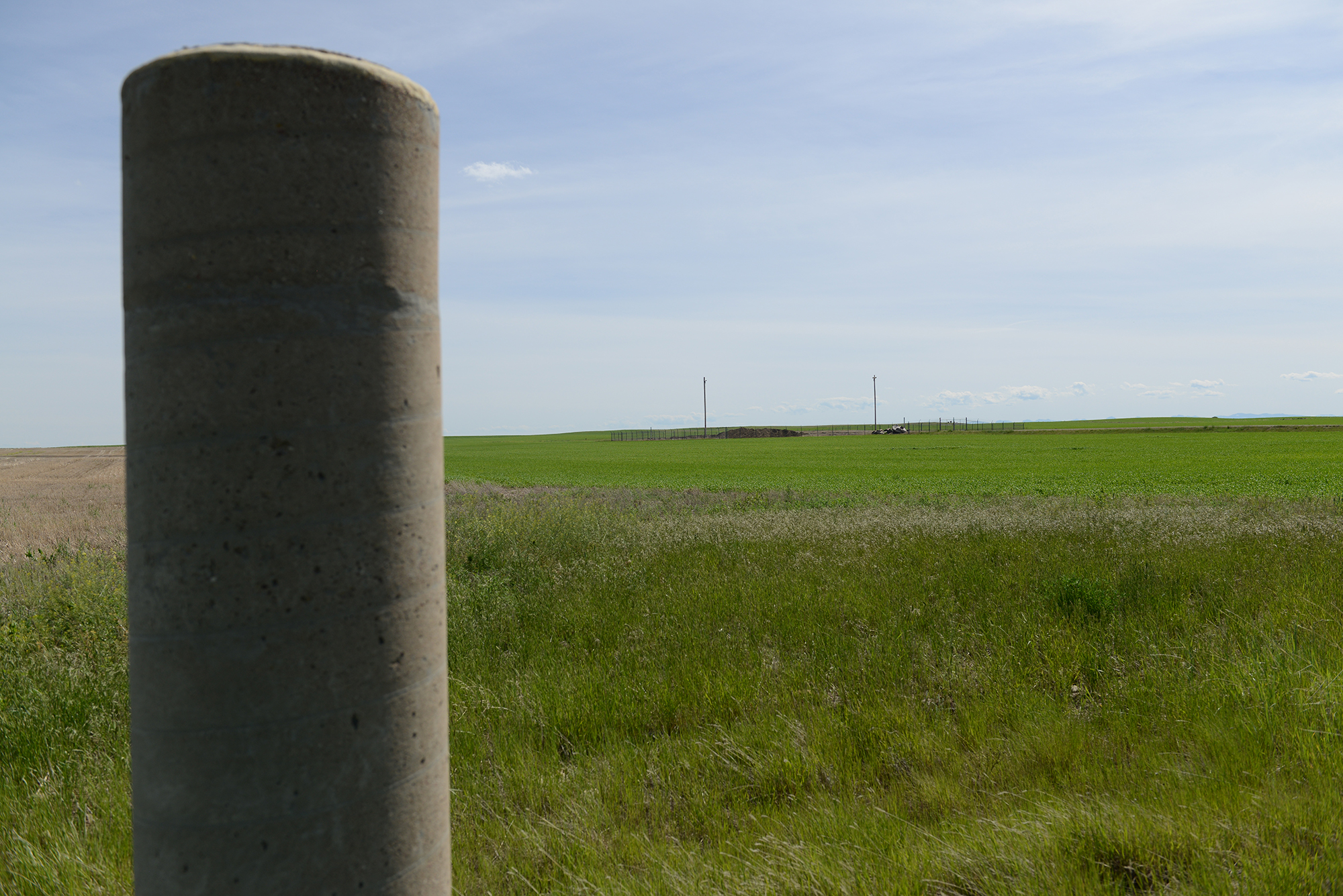
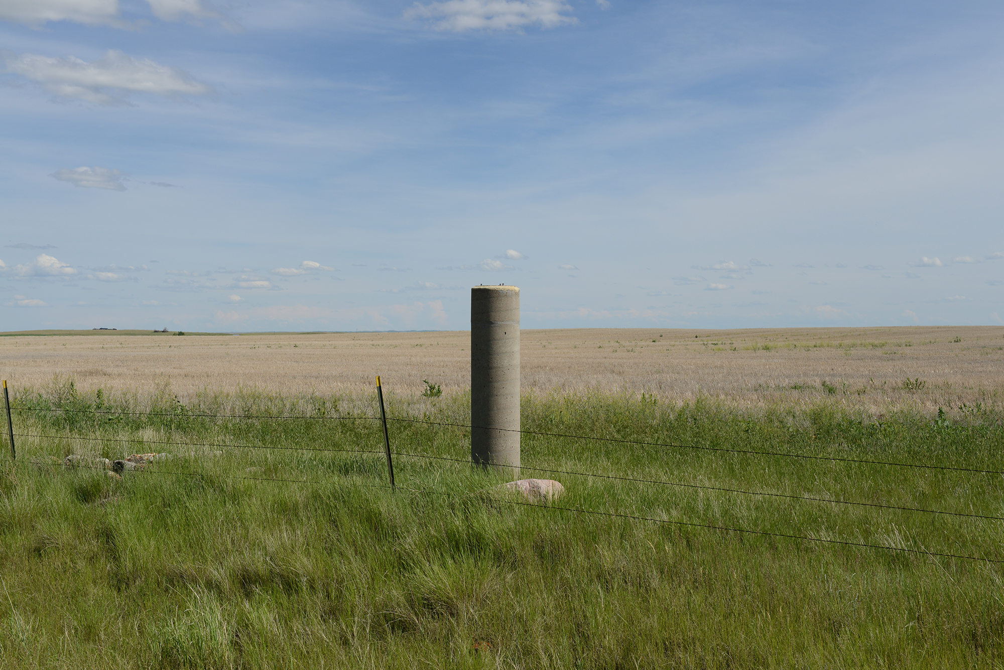
P10 Launch Facility Concrete Alignment Monument With Launch Facility In The Distance
Click on the image for a larger view
The image above gives the reader the perspective of the distance of a External Concrete Alignment Monument from the Launch Facility. A targeting device (a small battery operated light source) was bolted to the top of the monument. This allowed the targeting team to use their theodolite mounted to the "A Stand" monument, in which they would site the target attached to each of the two concrete monuments positioned at a significant distance (1000 to 1500 feet or more) from the Launch Facility. This particular monument provided easy access to it. It was located just off of the county road. This was not always the case. Some monuments would be located out in the middle of a rancher's field, requiring the targeting technician to either hike or drive out to the monument. This could turn out to be quite an adventure, given it was muddy and wet, cold and frozen, and/or dark out.
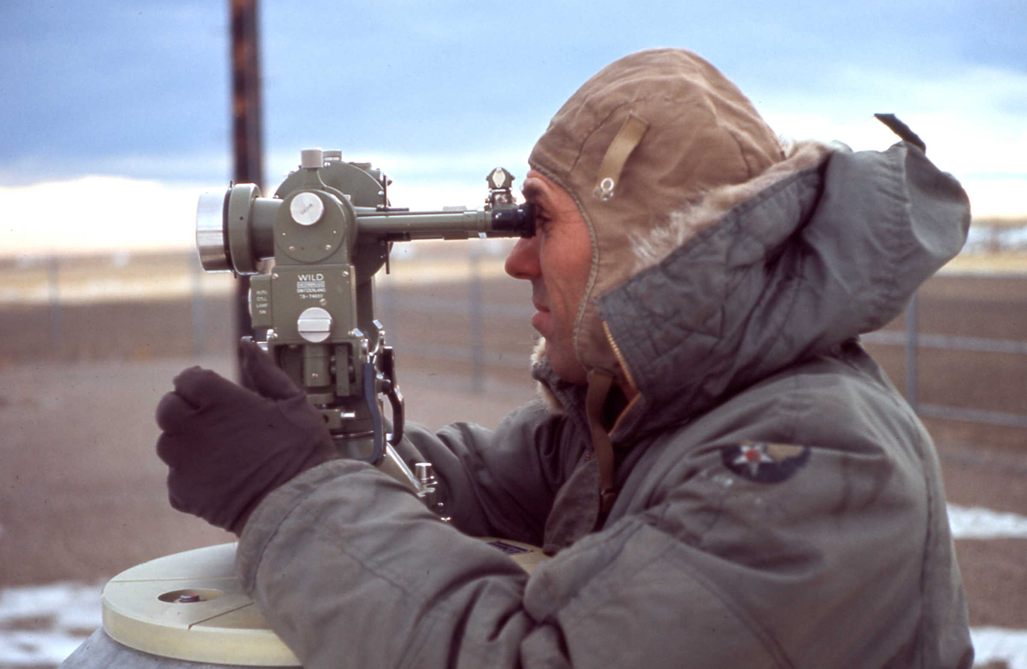
Theodolite Attached To The "A" Stand (monument)
Click on the image for a larger view
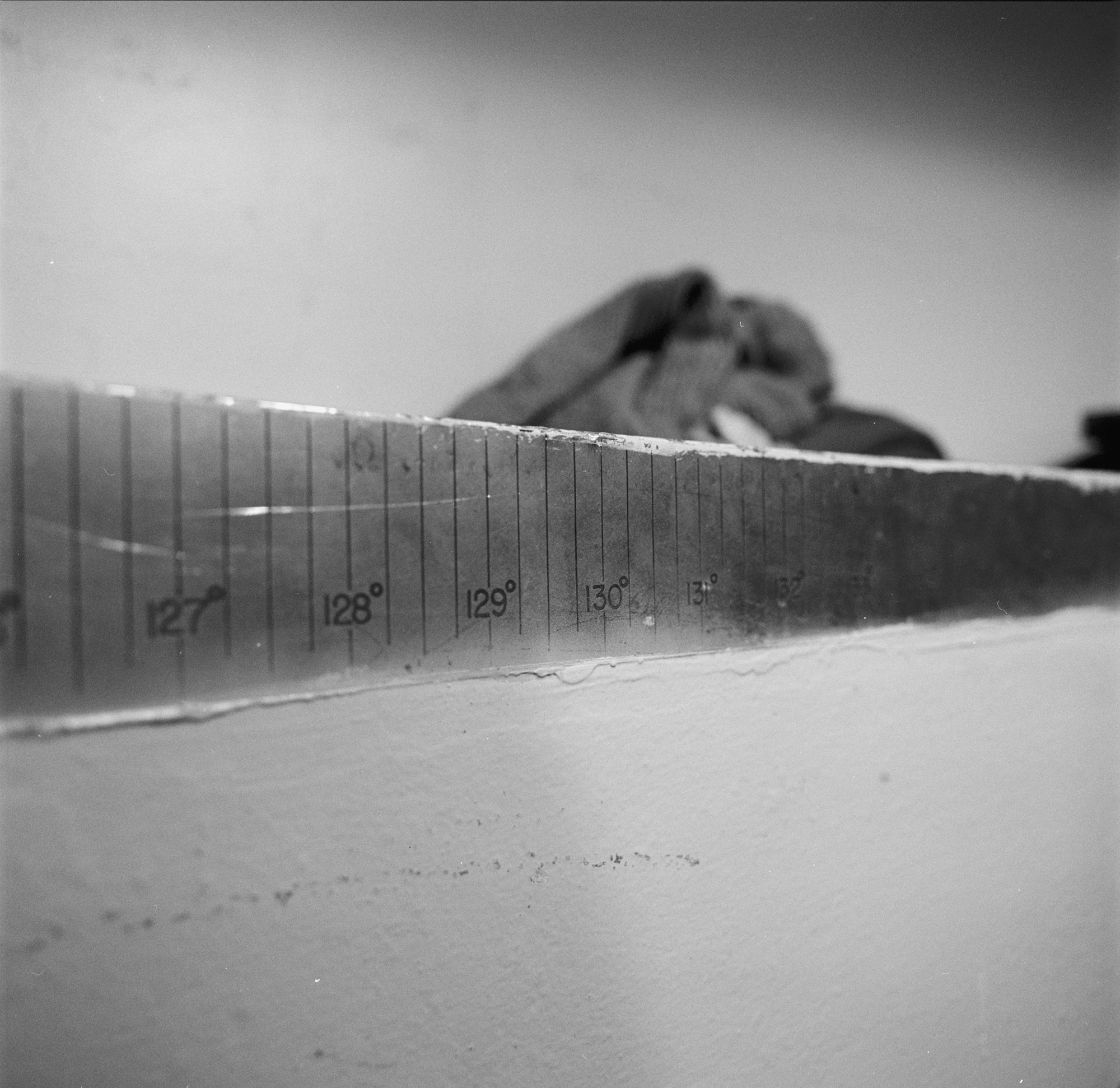
The image above is of the T3 Wild theodolite. Wild is pronounced "vildt" This instrument was made in Switzerland, and during that time period the Wild was one of the highest quality theodolites available. The theodolite is bolted to the concrete monument, and in the image above the theodolite is being used to shoot most of the angles used, (also called directions) and azimuths (which is an angle measured clock wise from north) of which was necessary to provide an azimuth reference down inside the Launcher Equipment Room.
The theodolite that is attached to the A Stand or A Point (at topside of the Launch Facility), is used to site the two external concrete alignment monuments that were located approximately 1000 to 1500 feet away from the Launch Facility. An example of how these concrete monuments were placed, would find at some Launch Facilities one alignment monument would be located east of the LF, while the second monument could be located to the south of the Launch Facility. The distance from the Launch Facility to the concrete monuments, as well as the distance between the two respective monuments from each other, was designed as such to provide the targeting and alignment technicians an accurate external azimuth.
In the early stages of the Minuteman missile design phases, the Air Force were thinking that the Minuteman missile could be given targeting coordinates by utilizing Polaris, the North Star. When it became obvious that the targeting technicians could not site the North Star from down inside the Launch Facility, they utilized the External Reference Azimuth system that is described above.
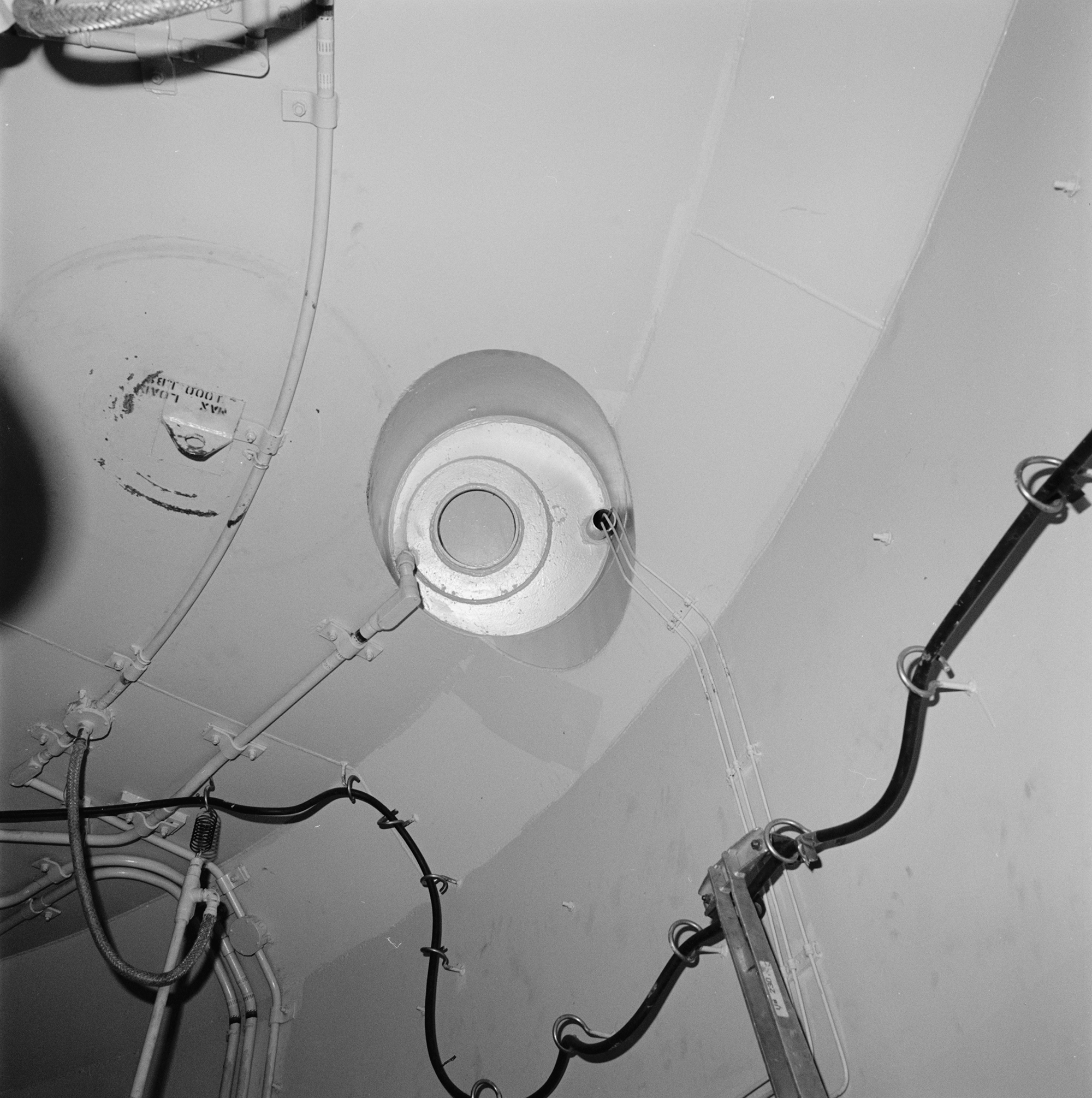
"Polaris" Site Tube
Click on the image for a larger view
The image above is of the "Polaris" site tube, which allowed the targeting technicians to shoot a light beam down inside the LF, into the Upper Launcher Equipment Room. Based on the readings the targeting technician was getting from the A Stand theodolite (which established its readings from the two concrete alignment monuments in the field) the two technicians could establish a azimuth reference. This would be configured into their targeting procedure that determined where the location of the North Star was in relationship to that specific Minuteman missile.
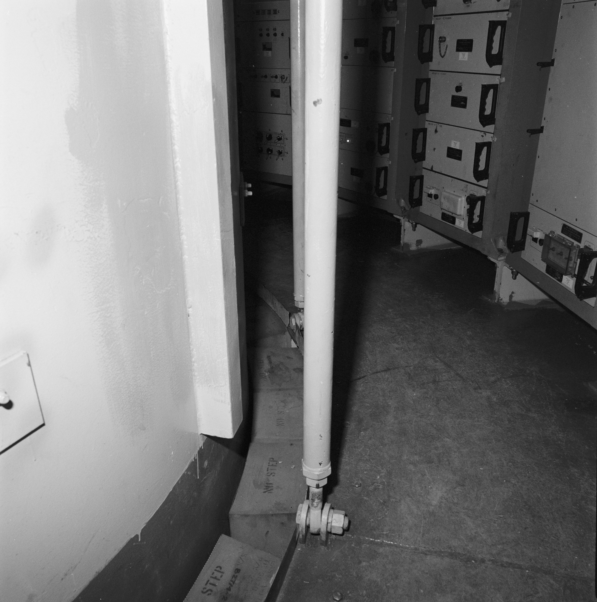
Upper Level Rattle Space
Click on the image for a larger view
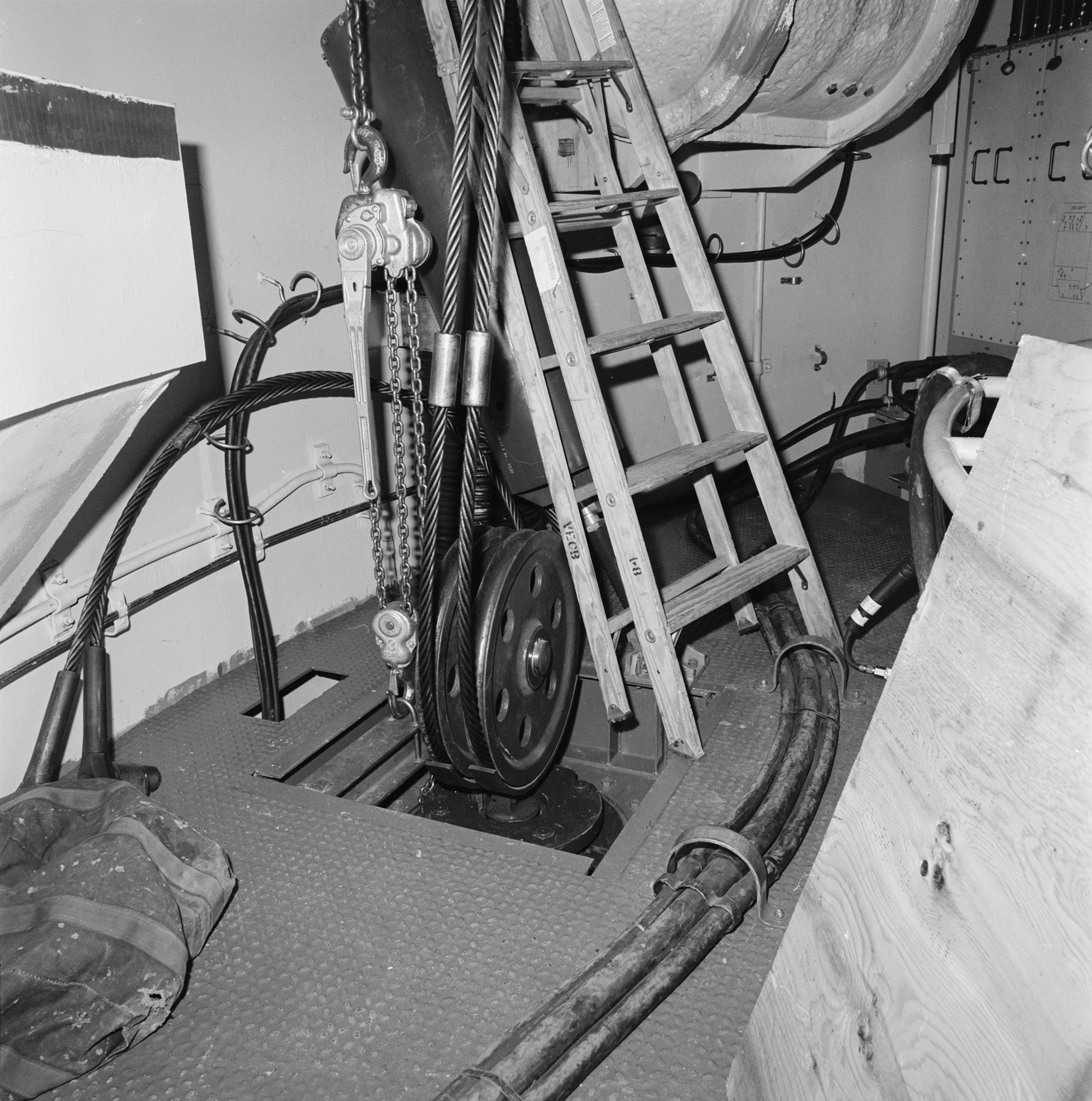
The image above is of the upper level rattle space. To the left is the actual Launch Tube itself. The Upper Level Launcher Equipment Room is suspended as such, so that it is isolated from the launch tube and can move separate from the Launch Tube. Again, this feature was incorporated into the construction of the Launch Facility providing protection by isolating the various components, in the event that there is a nuclear strike close by. This feature allows the Launch Facility to better absorb and isolate a concussive blast.
Upper Level Retractor Cables
Click on the image for a larger view
The retractor cables shown in the image above, are a part of the system that is connected to the Launcher Closure Door. In the event of the need for a launch, these retractor cables would pull down a huge metal pin that locks the 110 ton Launcher Closure Door closed. Once the pin is retracted, the ballistic gas generator forces the door open.
Upper Level Electronics Rack
Click on the image for a larger view
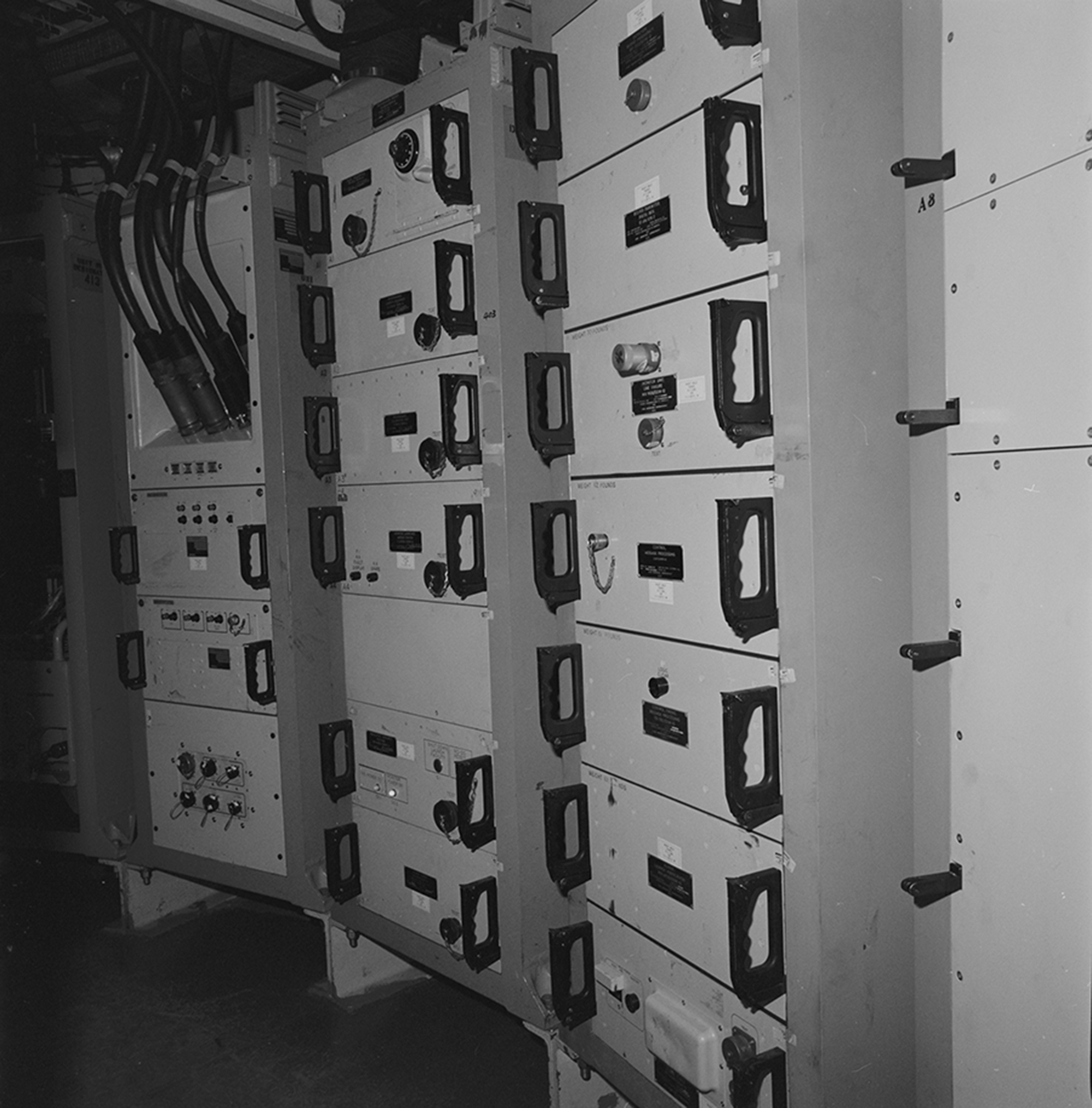
The image above shows one of a number of electronics racks located in the Upper Level Equipment Room. The rack furthest to the left in this image, houses the Guidance and Control Coupler.
Upper Level Air Conditioning Control Panel
Click on the image for a larger view
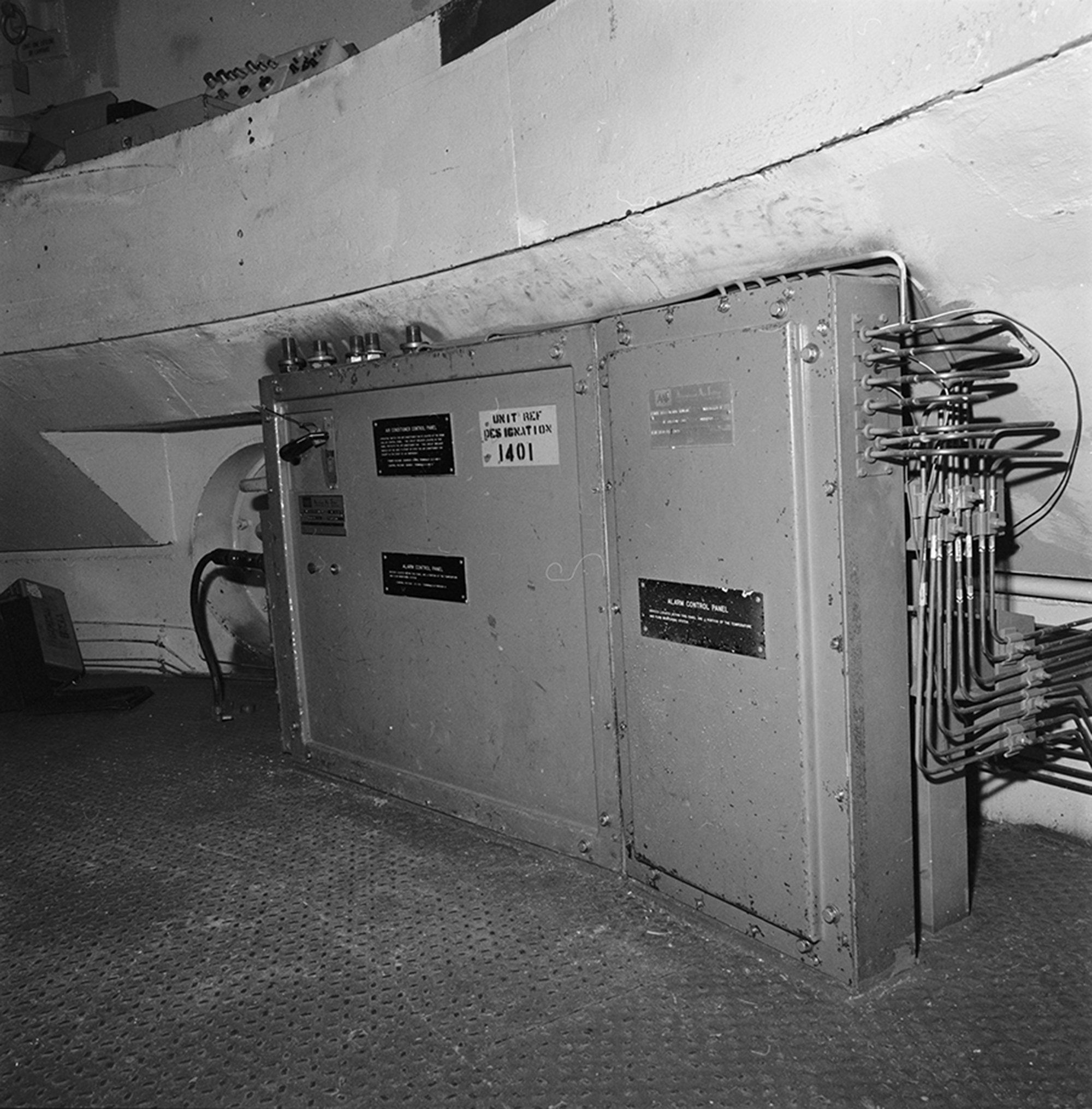
One final photo to look at, is of an image of an older piece of equipment that one will no longer find in the current Upper Launcher Equipment Room at the Minuteman Launch Facilities present day. This component was the Air Conditioning Control Panel, which provided the cooling capacity necessary to cool the Guidance and Control system of the Minuteman missile. Given the missile was standing ready to launch at a given notice, there was a need to assure that the Guidance and Control system did not overheat.
To view the equipment found in the Lower Launcher Equipment Room, follow the link below.